What is an ammeter: circuit diagram and it's type Circuit parallel series ammeter diagram capacitors equivalent find capacitor capacitance its study Circuit ammeter diagram series its negative terminal of ammeter in circuit diagram
Why Ammeter Connected to the Positive Terminal of the Battery? - The
Ammeter circuit diagram Ammeter circuit diagram Ammeter vs voltmeter
Voltmeter digital ammeter make circuit circuits homemade module segment led using diagram ac diy projects electronic ic displays arduino schematics
Ammeter meter ampere definitionAmmeter symbol Ammeter principle sponsored⭐ circuit diagram with ammeter ⭐.
Ammeter ammeters dc physics voltmeters circuit connect connected figure resistance should internal voltage across source shown electric connection chapter circuitsHow to make a digital voltmeter, ammeter circuit module Ammeter- definition and working principleWhat is an ammeter? symbol, circuit diagram, types and applications.

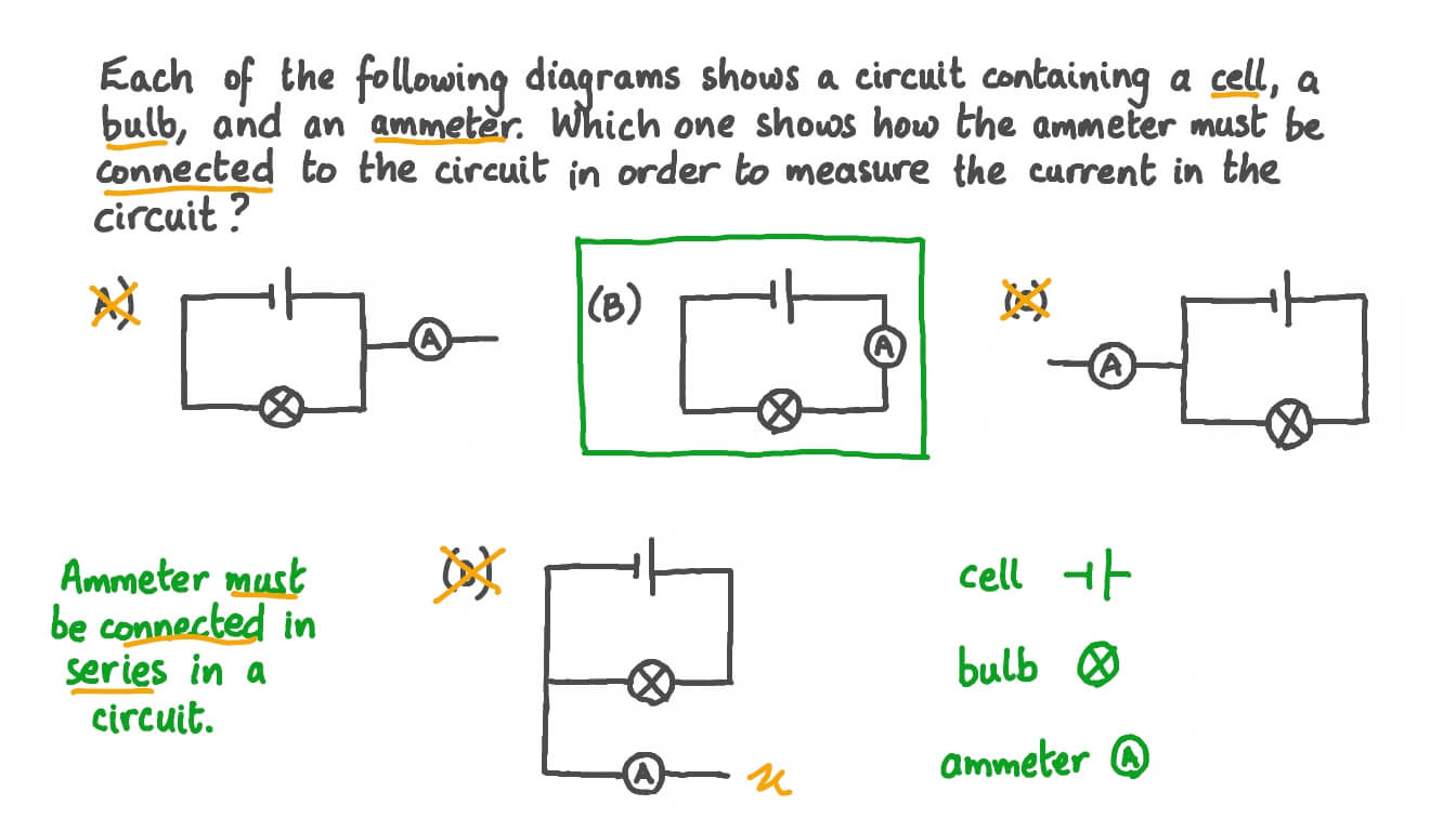
Which circuit will not show current in ammeter ?
What is ammeter?Ammeter definition electrical figure principle working series current basic measured into above gif so inserted Draw the symbol of commonly used components in electric circuit diagramAmmeter and voltmeter circuit diagram.
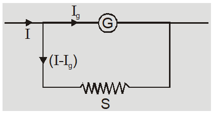
21.4 dc voltmeters and ammeters – college physicsAmmeter circuit resistance connection low kept because shunt Circuit ammeter current test measure use electrical usage circuits milliamps basic strip terminal electric equipment should experiment electronics textbook alsoAmmeter connection in circuit.

Ammeter circuit diagram
The potential difference across the terminals of an nonBasic ammeter use worksheet Ammeter usage : basic concepts and test equipmentDoubt solutions.
Solved task 1: noticing the effect of ammeter on circuit 1.Ammeter circuit voltmeter diagram current between difference gif connected must electrical level does resistance low very so connect vs Which circuit will not show current in ammeter ?How is an ammeter connected in a circuit how is a voltmeter connected.

Ammeter circuit diagram
Ammeter diagramAmmeter connection diagram with selector switch and ct What is an ammeter: circuit diagram and it's typeElectrical meters.
Why ammeter connected to the positive terminal of the battery?Which of these circuit schematics has an ammeter Ammeter circuit diagramAmmeter use using meter basic amps reading amp series picture measure connecting worksheet dc bulb load problem like battery electricity.

Ammeter function symbol & definition
Ammeter in a circuit diagramSymbol of ammeter .
.